UK's No.1 Mobility Shop
Here we have put together an information page to help you with room layouts measurements and more. If you require any more information please email
References are to WC compartment unless otherwise stated.
Fixtures and fittings should be positioned so they can be used by a person seated in a wheelchair.
Height and similar dimensions are from finished floor level/wall surfaces and apply to a non-automated compartment.
The BS8300:2001 Standard requires that all new disabled WC installations are fitted with an emergency assistance alarm. This Disabled WC Alarm Kit provides a compliant, reliable and easy to use disabled persons toilet alarm which contains the following devices:
Controller
Combined power supply and controller with reset button audible alarm & large diameter LED.
Ceiling Pull Swith with LED.
Ceiling Mounted Pull Cord with hight brightness LED.
Reset Point with LED.
Reset Button & LED to reset calls locally.
Overdoor Light/ Sounder.
Triangular Lens with integral sounder, to attract attention.
Features
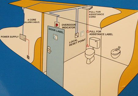
The controller should be located so that it is easily seen & heard by people able to give assistance, & indicates where help is required. The unit is not suitable for exterior location unless suitably protected against water ingress.
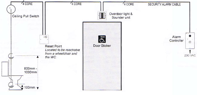
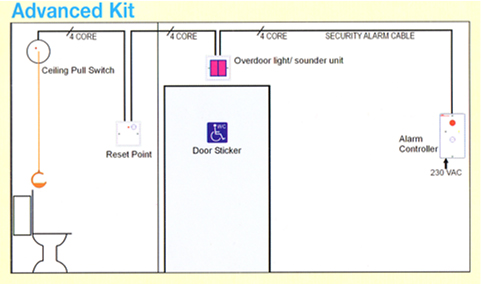
The Ceiling Pull Swith must be located so that it can be operated from WC and from an adjacent floor area. The ceiling Pull Switch is supplied with two G pulls, one should be set a height between 800 - 1000mm & the other set 100mm above the floor level.
The Overdoor Light/ Sounder should be located so that it is easily seen and heard by people able to give assistance and indicates where help is required. Normally above the door outside the WC.
The Reset Point should be located inside the WC area so that it is reachable from both a wheelchair and the WC.
Operation
Under normal conditions, the Controller 'on' LED will illuminate while the sounder & LED are off. When the ceiling Pull Switch is activated within the toilet area, the Controller audible sounder & LED will operate. The Overdoor Light / Sounder will also operate simultaneously. The call may be reset at the Controller and/ or the Reset Point within the toilet area, depending on reset configuration.
Battery Life
The battery is continuously monitored using the 'on' LED when this is dim or extinguished, the battery should be replaced. Only use an Alkaline Type A23 12 volt battery only which will typically provide 24 hours standby.
System Expansion
Additional devices can be added to the disabled WC alarm kit (Two extra ceiling pulls) or (One ceing pull switch and Overdoor Light / Sounder)
Installation - First Fix
Electrical back-boxes are required for the following items and these must be ordered seperately. The Controller requires 35mm depth double gang flush box or 'round corned' plastic surface box. The Overdoor Light and Reset Point require 25mm depth single gang flush box or 'round corned' plastic surface box. The ceiling pull Switch is self- contained with its own surface mounting enclosure.
Installation - Controller Mains Wiring
All mains wiring should be provided in accordance with the current edition of the lEE Wiring Regulations, or in accordance with the relevant national wiring regulations.
Connection to the mains supply MUST Not be made with a plug and socket. The mains supply should be exclusive to this unit.
The general requirement for the mains supply to the Controller is fixed wiring, using 3 core PVC cable not less than 0.75mm² fed from an isolating switched fusespur at 3 Amps. This should be marked appropriately and secure from unauthorised operation. All external wiring brought into the unit must be adequately insulated with PVC or Neoprene. If core cable & a good quality plastic backbox is used, the earth connection MUST terminate to the marked earth terminal on the Controller PCB. If a metal back box is used, the earth connection MUST be also made to the earth bonding point on the back box.
Installtion - Low Voltage Wiring
All low voltage , wiring to the Controller must be carefully planned before installation commences. An example wiring configuration, showing how ancillary devices are connected to the unit, is shown below. Always segregate low voltage wiring from mains wiring. For simplicity, the low voltage connector can be pulled from the printed circuit board.
Low Voltage Cable
Usse 4 and 6 core security alarm cable 7/0.2 or similar.
Reset Button Link
Where a seperate reset point is included in the alarm system (e.g) the reset button on the Controller can be disabled to ensure that only the reset point can reset the call. To disable the Controller reset button, remove the reset jumper by pulling the link away from the circuit board. For all reset points to operate, leave link in place.
Sound/ Light Link (Mode)
The Controller has the ability to either give a flashing light and sound output or a constant light and sound output. For constant light / sound, leave the mode jumper link fitted. For flashing light and pulsing sound, remove the jumper by pulling the jumper away from the circuit board.
Self Test
It is possible to confirm the operation of all sounders and LED lights in the system by pressing the reset button (on the Controller) twice in quick succession. Each light/sounder in the system will operate twice. e.g Two flashes on the ceiling pull switch LED.